|
|
Doug the Digger |
Upon the reception of the 2015 BEST kit at kick-off day, Raider Robotics immediately began the process of providing an efficient method of collecting all of the ores in the game, as well as making repairs to the mine, and collection of core samples. The team decided to focus on the collection of the ores and overlook the repairs to the mine and the collection of core samples. This decision was reached due to the narrowing of the tunnels as they go deeper into the mine. When we left kick-off day, the team presented a few questions that ultimately led to our final design:
- How can we make the robot mobile on the ground?
- What will be a sturdy, yet lightweight material to build the body from?
- How do we best collect the ore pieces?
- How should the robot be programmed?
While several ideas were thrown around, the ultimate decision was to make the robot have a four wheel base, with two powered motors. The first idea that was mentioned was to have tank treads as a means of mobility. This idea was dropped because of the tendency to get stuck on the thresholds of the tunnel entrances. From past experience, we mentioned the concept of having three wheels, two of which are motor powered and a single free wheel for balance. This was ruled as an insufficient method due to the need for a more rugged base. We settled on having four wheels. The two wheels powered by motors are operated by the small round motors. In previous competitions, our robot struggled to lift objects due to the placement of the small motors on the arm and large motors on the drive train. This problem will be eliminated by replacing the large motors with the small ones. The wheels are made from the thickest piece of plywood supplied in the consumable kit. They are 6 inches on the diameter and mounted at the center onto the body of the robot. They are covered on the ends with friction tape to ensure a good grip with the game field and allow for traveling over the thresholds of the tunnels.
During the construction phase, we failed to line up the free wheels horizontally. When the program was placed onto the controller, and tested, the robot was struggling to turn properly due to one of the two free wheels not touching the ground. We then drilled another hole in the body of the robot and attached a set screw to hold the axle down into the correct hole. This was to correct the issue of all wheels not touching the ground. This did not fix the problem. We then resorted to only having three wheels in an effort to balance the robot. When we drilled a hole in the center of the bottom of the robot to make room for the third wheel. We used the axle that was already cut to attach the roller blade wheel from the returnable kit as our third wheel. This solved the mobility problem.
What will be a sturdy, yet lightweight material to make the body from?
This was a point of great contention amongst the build and design team. There was a split about whether or not to make a cube will all sides made of wood or leave a side open. After a vote, the group finally elected to make a cube with all sides enclosed. We used the thick plywood provided in the kit to make the body from. We determined that due to our plans for our scoop, we would need a box with dimensions of 13 inches by 14 inches, by 10 inches. This ensures that the robot is able to hit the lever that releases the coal chute and allows for enough height from the ground to tip the magnetite tube.
Once we constructed the robot, we realized that it was entirely too heavy. In order to fix the problem with weight, we drilled holes into the body to reduce the weight. We didn’t want the robot body to weigh too much, handicapping the rest of the robot due to the weight restriction in the general rules.
How do we best collect the ore pieces?
This was the most debated component of the robot. Initial designs had a claw type structure that would pick up pieces of ore and store them into a box on the body of the robot. Then the robot would be able to dump the collected pieces into the RSB for scoring by the spotter. When we mapped out the number of motors we would need to make that design, it was eliminated for one that takes less motor use and more efficiency.
The next design was to build a scoop like that on a bobcat tractor. The scoop would be able to collect more than one ore piece at a time and dump them into a box on the bed of the robot body. The box would have the ability to tilt like a dump truck. This concept was also omitted due to the excessive use of motors.
The final design that we accepted was the keep the bobcat style scoop. But, instead of a box, we would just carry the pieces that we collected from one level back to the RSB for scoring. This reduces the weight of the robot significantly as well as reduce the number of motors. We chose to make the scoop from the ¼ inch polypropylene plastic. Our initial design of the scoop turned out to be too short to fill the horizontal gap between the plywood arms that were to attach it to the body of the robot. We did not account for the thickness of the plywood used in the body when we cut the plastic for the scoop. We had to make a patch on the scoop using more plastic and some zip ties. This allowed for the scoop to successfully fit in between the arms and made for a smooth motion of the body as a whole.
The scoop allows for picking up all ores that are on the ground as well as tipping over the chalcopyrite box and the magnetite pipe. We plan to use the scoop to collect one ore at a time, spending no more than 30 seconds on any one ore.
How should the robot be programmed?
The programmers did not begin their work until the final robot design was constructed, with the exception of oversight to ensure that programming would be possible for the design. When programming began, the lead programmer had an immediate game plan. The team uses EasyC V.5 to program the robot.
The two drive motors for the chassis would be programmed using a “Joystick to Motor” function. This allows them to be controlled with the joysticks on the hand-held controller. The driving style is that of a tank. This means that when both joysticks are pushed forward, the robot moves forward. When the joysticks are both pushed back, the robot moves backwards. The motors are programmed at full speed for the drive train. The right motor and left motor are programmed to function in opposite directions to ensure fluid forward and backward motion as well as a zero degree turning ability.
The arms on the upper section of the robot body are responsible for lifting the scoop. These motors are programmed using two “Digital to Motor” functions. This allows the arms upward and downward motion to be controlled by the digital buttons on back left of the controller. Again, to ensure fluid motion and simultaneous motion of the two motors, they were programmed to work in opposite directions. Unlike the drive motors, the arm motors are programmed at speed values of 70 and -70 to allow for more driver control and accuracy when lifting and lowering the arm.
The scoop is operated by two servo motors. The motors are facing opposing directions, and like the other motors in the robot, we had to program these motors to rotate in opposite directions. Using a “digital to servo” option for both servo motors, the buttons on the back right of the controller to control the upward and downward motion of the scoop. These motors were programmed to a rotation speed value of 60 and -60 to ensure a slow and smooth motion of the scoop. This will help to avoid spilling the contents of the scoop onto the field after collection of ores.
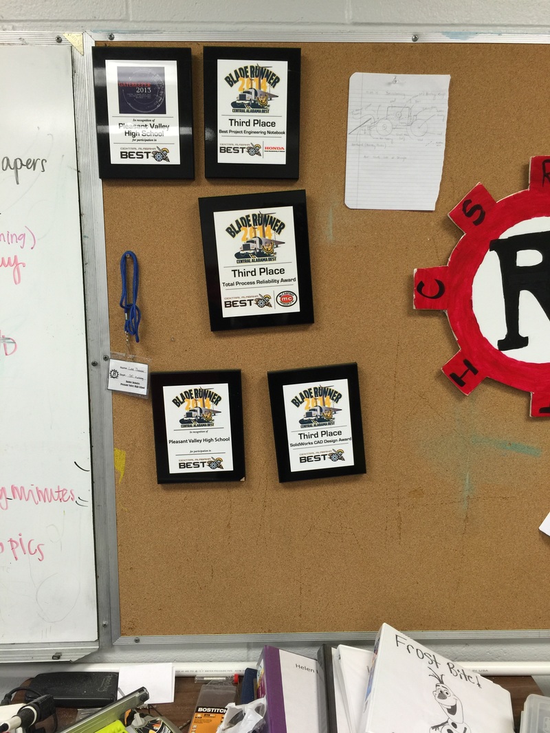
Awards RECEIVED:
|
2014 Season:
- BEST Gatekeeper Participation Award 2015 Season: - BEST Bladerunner Participation Award - 3rd Place BEST Engineering Notebook - 3rd Place CAD Design - 3rd Place Most Reliable Robot |
|
